- Table of Contents
- 1. Introduction
- 2. Analog to digital
- 3. Connecting phones
- 4. Delays and priority
- A. IPv4
- B. UDP
- C. RTP
- List of Tables
- 2-1. Codec comparison
- 3-1. Naming conventions
- 3-2. Protocol overhead in bits per packet
- 3-3. Sample rate and data transmitted
- 4-1. IPv4 ToS field
- 4-2. IPv4 ToS Precedence
- A-1. IPv4 header
- B-1. UDP header
- C-1. RTP header
Chapter 1. Introduction
This document is written as a decision document. I have put together all data relevant in choosing VoIP as an application. With a comparison of most techniques involved. It is hoped that after reading this document the reader is capable of making a decision which techniques are needed to roll out VoIP within their specific environment. VoIP is not a one size fits all technology so careful planning can make a big difference between success or failure to deploy VoIP.
What is VoIP
VoIP (Voice over Internet Protocol) is a very small name that covers a wide range of techniques for making phone calls over an IP based network.
The largest IP network is the Internet, VoIP makes it possible to have a life conversation with someone on the Internet, in the same country or at the otherside of the world. So it is an addition to the e-mail and chat (MSN, ICQ, etc.) functionalities.
How it was
It all started with Bell and with the POTS (Plain Old Telephone System). With POTS I mean a telephone connected to a wire that runs to the wall and then the magic starts. When you dial or touch a number you get someone on the other end and you can talk to eachother. That is POTS for you in a nutshell.
In this section we are going to explain a bit of the magic. This will help you better understand everything involved in VoIP networking. The following picture shows a more detailed picture of how a telephony system works.
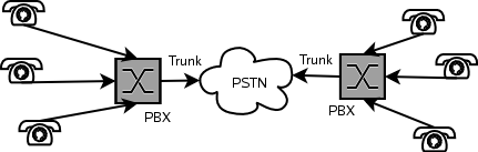
The first new element is the PBX which is short for Private Branch eXchange. A PBX gives you the option to connect more phones to the line you get from your local telecom supplier, ofcourse only one single phone can use the outside line, but you now have the choice of which phone you use. It also gives you the ability to call from one phone to the other without using the telecom suppliers line. So it is free of charge.
The PBX can also be used to have more lines coming from your telco (Telecom Company). But more lines means more costs. A solution to this problem was found in TDM (Time Devision Multiplexing). TDM sends more phone calls across a single line by using so called time slots. Every conversation gets a time slice on the link. When that happens fast enough your ears will not hear that the conversation was cut into pieces.
The TDM signal is then send across the PSTN (Public Switched Telephony Network) using a trunk line. Actually the trunk line is the connection between two telephone switches. And the line between your closed telephone switch and your telephone is called the Local Loop. The fact that it is called a PSTN, already indicates the fact that we are talking about switching, a PBX is in it's most basic functionality nothing more than a switch. A switch that switches between different lines and telephones.
Why change?
Price. Since most people in a western world do have a broadband connection to the Internet and the amount of time it takes to send a packet across the Internet (latency) to another computer is so little, voice applications are possible. Since everybody is already paying for her or his DSL-link, why should we also pay for telephony, while we can use the same link for that?
Another reason might be flexibility. The old telephone system tied a number to a phone. If you where not near the phone, you would miss the call. Mobile phones have solved this problem. But it didn't solve it for those areas where your mobile phone provider does not have an antenna. VoIP might be a welcome addition in those areas. If there is Internet, but no mobile phone system, like in some developing countries, VoIP might just be the solution.
A VoIP call
As with normal phone conversations VoIP also consists of two functions, which you normally take for granted: First you have to be connected, before you can talk.
VoIP is very different from a normal phone call. Where the telecom operators are already used to digitize voice before it is send across the large cables they operate, all is send in a nice and orderly fashion. The problem with IP is that it promises to make an best effort to get the data across. It doesn't promise it gets it there, nor does it promise to get it there intact, and even more troublesome for our voice call it doesn't promise to get it there in the order in which the data was send.
All these parts will be discussed in the document. We will start with the analog to digital conversion, then discuss how we can get the signalling right and last we will discuss what techniques can be used to make sure phone calls can be made over such an unreliable network.
Chapter 2. Analog to digital
To send voice over an IP network, one needs to convert the analog voice signal to a digital (one and zero) representation. To send it across a network it has to be addressed. And as with mail, there are several ways to do this. One can use the known postman to get it to its destination, or one could use an express service to get it there fast. The same is true for data across a network.
Converting the analog voice signal to digital is a very broad subject. We will only cover the basics here. Just enough to give you an idea of what is going on. For more information see the Read More section at the end of this section.
There are three ways to encode speech. One could use a way of encoding the waveform, which the simplest form is known as Pulse Code Modulation. More complex codings are ADPCM and DPCM. This technique can produce high quality encodings, at the cost of the bandwidth used.
Another way is to encode how the source was generated. Source coders for speech are called vocoders, and achieve a very low bitrate, at the cost of the quality. Since those coders are not used for normal human telephone conversations, due to the low quality, we will not go into this technique.
And the last version is a hybrid solution between the two techniques. The most important version of a hybrid solution is CELP, which is the basis for most current speech codecs used in VoIP solutions. They form a nice balance between bandwidth use and quality.
We will start off with PCM since this shows you in a very clear manner what the problems are with bandwidth vs. quality. And it gives you a good basis for understanding the CELP solutions.
PCM: Pulse Code Modulation techniques
To convert the 4 kHz voice signal of a phone call t a digital format we need a sampling rate of 8 kHz (for Nyquist) or 8000 samples per second. Encoding that into a 8 bits representation, means that 8x8000=64.000 bits per second need to be used to achieve near perfect voice encoding. This is what is called PCM encoding, which is the most used standard in the telecom world, the 64 kbps time slot.
μ-law for North America and a-law for Europe are variants of PCM used to code the analog signal on a logarithmic scale using 12 or 13 bits instead of 8 bits (see Standard ITU-T G.711)
Out of this basic standard all kinds of different techniques grew to create standards that used less bandwidth, but maintained more or less the same quality.
CELP: Codebook Excited Linear Prediction techniques
CELP uses a very complex scheme of encoding through which it is able to produce voice streams of less then 16 kbps. The downside is that delay is added through the extra processing needed. G.728 is an good examle of a CELP codec, which has an delay of less then 2 ms.
Which codec?
Table 2-1. Codec comparison
| Name | Standard | organisation | Sampling rate (kHz) | Bit rate (kbps) | Frame size (ms) | Delay (ms) |
|---|---|---|---|---|---|---|
| PCM | G.711 | ITU | 8 | 48, 64 | 20 | 0 |
| Subband ADPCM | G.722 | ITU | 16 | 48, 56, 64 | 15 | 0 |
| ADPCM | G.726 a-law or μ-law | ITU | 8 | 16-40 kbps | 20 | 0 |
| MP-MLQ | G.723.1 | ITU | 8 | 6.3 | 30 | 7.5 |
| ACELP | G.723.1 | ITU | 8 | 5.3 | 30 | 7.5 |
| LD-CELP | G.728 | ITU | 8 | 16 | 18.75 | 0.625 |
| CS-ACELP | G.729 | ITU | 8 | 8 | 10 | 5 |
| LPC-10 | ? | ? | ? | 2.5 | ? | ? |
| GSM | DCS1800, PCS1900 | ETSI | 8 | 13 | 20 | ? |
| iLBC | RFC3951 | IETF | 8 | 13.3 | 30 | 30 |
| iLBC | RFC3951 | IETF | 8 | 15.2 | 20 | 20 |
| Speex | IETF draft | XIPH.org | 8, 16, 32 | 2.15-24.6 (NB) 4-44.2 (WB) | 30(?) | 30 (NB) 34 (WB) |
The codec that best suites your needs is highly dependend on the type of application you are using. With every decision you win on one point and loose on another. The only thing I can do is to give some general considerations.
First we have to consider what the most important factor is: quality or bandwidth.
Minimize bandwidth
If you want to communicate across a network that has a high loss percentage you might want to use iLBC. iLBC frames are encoded completely independently. This provides better quality when 10% or more of the packets are being dropped.
If you have however good quality connections, with little of no loss of data, Speex might be more what you are looking for. iLBC is suboptimal for clean line conditions.
Read more
http://www-mobile.ecs.soton.ac.uk/speech_codecs/
http://www.speex.org/docs.html
http://www.ilbcfreeware.org/documentation.html
http://www.shoshin.uwaterloo.ca/~jscouria/GSM/index.html
Chapter 3. Connecting phones
The first part in a telephone conversation is the telephone. With the use of VoIP there are different ways of using the phone. The simplest and most flexible form is the use of a PC, some software (Softphone) and e.g. a headset. You PC needs to have a soundcard for this to work.
Another solution is to buy a IP-phone. This looks like a normal phone but it connects to ethernet instead of to the telephone line.
There are more options, but this are the most common ones. The next step in our conversation is the way we connect two VoIP phones together.
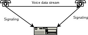
The easiest way to connect two VoIP phones is by using a Peer-to-peer network (P2P). This means that you have to have the IP address or DNS name of the other phone and you make a direct connection.

If you use a softphone you can ofcourse also use the old system and VoIP side-by-side. This might easy the migration, but remember that most people do not like headsets when they are at work. So you risk having two phones on every desk, one normal and one VoIP phone.
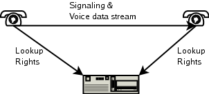
The gatekeeper solution brings you more flexibilty. Your phone registers itself at a central server and you get the information of the party you want to call from that server.
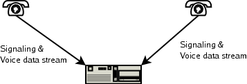
The most advanced system is a VoIP PBX. Now the central server takes over the PBX function of PSTN. Meaning it handles the signaling, and the routing of the actual data stream.
Replacing the entire telephone system with a VoIP solution is the most radical step. It means removing all your phones, cables and PBX solutions and replacing it with an entirely new system and probably a good bunch of additional cables too.
Another solution we would like to present is the use of VoIP for trunking. Meaning the PBX to PBX line is converted into a VoIP connection:
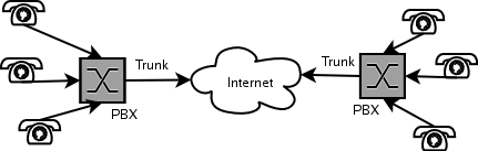
If you only want to change the trunking of your PBX, you have the easiest solution. The PBX needs to support VoIP, but that's it.
It all depends on what you want to achieve what the best solution is for you.
The most important things to look at are the codecs used and the protocols supported. And think about the future, life will change!
Protocol suites
At the time of writting there are two major protocols and one new commer that are describing the protocols used to setup a connection and how the voice data is transported to its final destination.
Within the protocol suites different approaches are choosen for call setup and tear down (signaling) and the transport of the actual voice data (data steaming). Luckily there are also all kinds of naming conventions, to make things more complex. To help you a bit we created an overview that hopefully clears the way in better understanding the different parts:
Table 3-1. Naming conventions
| Part | POTS | H.323 | SIP | IAX |
|---|---|---|---|---|
| Telephone | Telephone | Terminal | User Agent (UA): UAC (client that sends calls) and UAS (server that accepts calls) | Host |
| Phone to switch line | Localloop | Network(Ethernet) | Network(Ethernet) | Network(Ethernet) |
| Switch | PBX, PABX | Gateway (VoIP-PSTN, codec to codec conversion), Gatekeeper (VoIP-VoIP authorisation), MCU (Multipoint Control Unit enables conferencing) | Proxy server (switching and translation), Redirect server (returns addresses to contact to reach the UA), Registrar (Database with position where the UA is located) | PBX |
| Trunk | Trunk | ? | ? | Trunk |
Signaling protocols are also refered to as session protocols, since they are responsible for setting up and tearing down a connection. We will decsribe them from old to new with both their pros and cons. Remember however that standards change with new versions, so always check if what is written here is still correct.
H.323
Actually this title is not entirely correct. H.323 is much more then just a signaling protocol. H.323 is a teleconferencing protocol (Packet-based multimedia communications systems) describing how to use all kinds of communication techniques over an packet based (e.g. IP) network. This could be voice, video, chat, filesharing, whatever. H.323 contains a lot of different other standards for all the different parts, so it acts like an umbrella.
The signaling part consists of H.225.0 and Q.931 of the ITU. H.225.0 defines the way a phone connects to a PBX (or gatekeeper in H.323 terminology). If there is no PBX and the phones want to talk directly to one another H.225.0 is used with the use of Q.931, which is part of the ISDN signalling.
CUT:Until recently, network managers looking to roll out intelligent networks have relied heavily on the H.323 suite of protocols. With H.323, a compliant client, such as Microsoft NetMeeting, queries an H.323 gatekeeper for the address of a new user. The gatekeeper retrieves the address and forwards it to the client, which then establishes a session with the new client using H.225, one of the H.323 protocols. Once the session is established, another H.323 protocol, H.245, negotiates the available features of each client.
Additionally H.245 is used to negotiate the different media formats (codecs) to be used.
The actual transport of voice is done through RTCP and RTP, see the Transport overhead section.
H.323 supports the G.711, G.722, G.723, G.728 and G.729, audio codecs, while for video it supports H.261 and H.263.
Although very versatile and closely related to the telecom world standards, H.323 is a very complex protocol.
CUT: H.323 recreating a separate hierarchy of telephony name servers.
SIP (RFC 2543)
SIP (Session Initiation Protocol) is a text-encoded, highly extensible protocol. SIPs only responsibilty is to setup and tear down a connection. The actual voice data stream is handled by RTP and RTCP.
CUT:With SIP, each user is identified through a hierarchical URL that's built around elements such as a user's phone number or host name (for example, SIP:user@company.com). The similarity to an e-mail address makes SIP URLs easy to guess from a user's e-mail address.
CUT:The request is sent to the user's SIP server. The SIP server may be a proxy server, which receives the request and, using its own internal algorithms, determines the user's location. Alternatively, the SIP server may be a redirect server that returns to the client the appropriate SIP URL, which the user then queries. In either case, the server's address is learned by querying the DNS, the distributed database that matches high-level host names with the underlying IP address.
CUT:"Designated capabilities" refer to the functions that the user wants to invoke. The client software might support videoconferencing, for example, but the user may only want to use audio conferencing. Regardless, the user can always add functions - such as videoconferencing, whiteboarding, or a third user-by issuing another invite request to other users on the link.
CUT:SIP has two additional significant features. The first is SIP's ability to split, or "fork", an incoming call so that several extensions can be rung at once. The first extension to answer takes the call. This feature is handy if a user might be working between two locations (a lab and an office, for example), or where someone is ringing both a secretary and a boss.
SIP is a widely adopted protocol, with a lot of support and extensive documentation.
RTP (RFC 1889)
RTP (Realtime Transport Protocol) is a protocol implemented on top of UDP to have a semi-realtime transport over the unreliable IP and UDP protocols.
IAX
The IAX (Inter Asterisk eXchange) protocol is a new kid on the block. The design goals for IAX where to minimize the protocol overhead (see Transport overhead), to make it possible to use VoIP through NAT (Network Address Translation) firewalls, the ability to transport dialplan information, and to support efficient implementation of intercom and paging features.
The main reason for choosing IAX for most people however will be the NAT ability of IAX. Since RTP can only be used with additional software when located behind a NAT firewall.
Data vs. overhead considerations
This section does not take into account header compression, also we will base our calculations on IPv4 headers.
Digitized voice is first wrapped in an RTP (Real Time Protocol) or IAX header. This is put into an UDP envelope and then send across the network using IPv4. All these headers add overhead (actually the datalink layer adds another piece of overhead (ethernet: 112 bites)). To give you a quick overview of the amount of data we are talking about:
Table 3-2. Protocol overhead in bits per packet
| RTP | IAX | UDP | IP | Total |
|---|---|---|---|---|
| 96 | 64 | 160 | 320 | |
| Miniframe: 32 | 64 | 160 | 256 | |
| Fullframe: 96 | 64 | 160 | 320 |
Assuming that every packet we sent holds 20 milliseconds of voice samples, there are 50 packages per second needed. Every packet has the above mentioned overhead (e.g. 50 times 320 is 16 kbps overhead).
That means that for the RTP/UDP/IP combinarion we have 16 kbps header overhead, and for IAX/UDP/IP 12.8 kbps. Going back to our table on the different codecs, we have to add the header overhead. Especially for the CELP versions one can see that the header overhead is a very important factor in the total amount of data transmitted across the network.
Table 3-3. Sample rate and data transmitted
| Name | Standard | Sample rate (ms) | Frames/second | RTP Total (kbps) | IAX Total (kbps) |
|---|---|---|---|---|---|
| PCM | G.711 | 20 | 50 | 80 | 77.8 |
| Subband ADPCM | G.722 | 20 | 50 | ? | ? |
| ADPCM | G.726 a-law or μ-law | 20 | 50 | 48 | 44.8 |
| MPE/ACELP | G.723.1 | 30 | 33 | 16.27, 17.07 | 13.07, 13.87 |
| LD-CELP | H.728 | 20 | 50 | 32 | 28.8 |
| CS-ACELP | H.729 | 20 | 50 | 24 | 20.8 |
| GSM | ? | ? | ? | 29 | 25.8 |
| iLBC | RFC3951 | 30 | 33 | 23.86 | 20.66 |
| Speex | IETF draft | 30 | 33 | 3.750-40.6 (NB), 5.6-45.8 (WB) | 0.550-37.4 (NB), 2.4-42.6 (WB) |
RTCP provides feedback on the quality of the transmission link.
To reduce the amount of overhead one could increase the frame sizes (increasing the frame size, reduces the amount of packages per second send, and). The downside is that if a packet gets lost a larger part of a piece of the conversation is lost. Which means more noticeable audio problems.
Which protocol
Effectively the IAX(2) protocol uses the least overhead, the downside is that is not a open standard. It is created by the makers of the Asterisk PBX, so there might be little support for this protocol in devices.
H.323 is already considered absolete sinds the introduction of SIP, however there are still a lot of devices and applications that use the H.323 protocol so it all depends on the devices you have and that you want to support.
Chapter 4. Delays and priority
Delays within a VoIP network are introduced by two main factors. The first one is the delay introduced by the codec. And the last and most of the times biggest part is introduced by the network. It just takes time to send data from one point to the other. Within this section we will speak of latency when we mean the network delay and use codec delay for the delays introduced by the codec.
Another factor in the transmission of data across a network is the way the data is handled. Assume you are visiting a website and making a VoIP call. Then it is possible to send a packet to the website and then a VoIP packet one at a time. This means both have the same priority.
You could also imagine that you give the VoIP packets priority over the website packets, meaning effectively that the website packets are held back when there is a VoIP packet, and are only send when there are no more VoIP packets to be send. This is a very simple way of Quality of Service (QoS). Later on in this chapter we will describe more ways of using QoS to get the VoIP data across the network.
Latency
It takes time to transport data across a network. The longer the distance the more time. Ethernet, Internet, VSAT.
IPv4 TOS
According to [RFC791], the IPv4 TOS octet is divided into a 3 bit Precedence field and a 3 bit TOS field. The last two bits of the TOS octet are reserved for future use:
Table 4-1. IPv4 ToS field
| 0 | 1 | 2 | 3 | 4 | 5 | 6 | 7 |
|---|---|---|---|---|---|---|---|
| Precedence | 0 = Normal delay, 1 = Low delay | 0 = Normal throughput, 1 = High throughput | 0 = Normal reliability, 1 = High reliability | Future use | |||
The Precedence field is defined according to RFC 791 as:
and is only applicable within a network.Appendix A. IPv4
Table A-1. IPv4 header
| 0 | 1 | 2 | 3 | 4 | 5 | 6 | 7 | 8 | 9 | 10 | 11 | 12 | 13 | 14 | 15 | 16 | 17 | 18 | 19 | 20 | 21 | 22 | 23 | 24 | 25 | 26 | 27 | 28 | 29 | 30 | 31 |
|---|---|---|---|---|---|---|---|---|---|---|---|---|---|---|---|---|---|---|---|---|---|---|---|---|---|---|---|---|---|---|---|
| Octet | Octet | Octet | Octet | ||||||||||||||||||||||||||||
| Version | IHL | TOS | Total Length | ||||||||||||||||||||||||||||
| Identification | Flags | Fragment offset | |||||||||||||||||||||||||||||
| TTL | Protocol | Header checksum | |||||||||||||||||||||||||||||
| Source IP address | |||||||||||||||||||||||||||||||
| Destination IP address | |||||||||||||||||||||||||||||||
- Version
The IP version used: 4
- IHL
Ip Header Length: The IP header length in units of 4 octets. As shown in the table it would mean the amount of lines: 5
- TOS
Type Of Service: The quality of service request. All devices on the link have to support this before it is effective.
- Total Length
The total length of the datagram in octets (including header and payload).
- Identification
The refragmentation identifier. After fragmentation this identifier indicates which fragements belong together.
- Flags
The fragment flags.
- Fragment offset
The reordering number of a fragmented datagram.
- TTL
Time To Live: The amount of hops the datagram may pass through. This prevents endless living of datagrams.
- Protocol
Who is our upper protocol (e.g. UDP, TCP).
- Header checksum
The checksum for the header.
- Source address
The source.
- Destination address
The destination.
Appendix B. UDP
Table B-1. UDP header
| 0 | 1 | 2 | 3 | 4 | 5 | 6 | 7 | 8 | 9 | 10 | 11 | 12 | 13 | 14 | 15 | 16 | 17 | 18 | 19 | 20 | 21 | 22 | 23 | 24 | 25 | 26 | 27 | 28 | 29 | 30 | 31 |
|---|---|---|---|---|---|---|---|---|---|---|---|---|---|---|---|---|---|---|---|---|---|---|---|---|---|---|---|---|---|---|---|
| Octet | Octet | Octet | Octet | ||||||||||||||||||||||||||||
| Source port | Destination port | ||||||||||||||||||||||||||||||
| Length | Checksum | ||||||||||||||||||||||||||||||
- Source port
Identifies the higher layer process which originated the data.
- Destination port
Identifies with higher layer process to which this data is being transmitted.
- Length
The length in octets of the UDP data and payload (minimum 8).
- Checksum
Optional field supporting error detection.
Appendix C. RTP
Table C-1. RTP header
| 0 | 1 | 2 | 3 | 4 | 5 | 6 | 7 | 8 | 9 | 10 | 11 | 12 | 13 | 14 | 15 | 16 | 17 | 18 | 19 | 20 | 21 | 22 | 23 | 24 | 25 | 26 | 27 | 28 | 29 | 30 | 31 |
|---|---|---|---|---|---|---|---|---|---|---|---|---|---|---|---|---|---|---|---|---|---|---|---|---|---|---|---|---|---|---|---|
| Octet | Octet | Octet | Octet | ||||||||||||||||||||||||||||
| Version | P | X | CC | M | PT | Sequence number | |||||||||||||||||||||||||
| Timestamp | |||||||||||||||||||||||||||||||
| Synchronisation source (SSRC) number | |||||||||||||||||||||||||||||||
- Version
The RTP version: 2
- P
Padding: A parity bit.
- X
eXtension: The presence of a header extension
- CC
CC field is the number of CSRC identifiers following the fixed header. CSRC field are used, for example, in conference calls.
- M
Marker bit
- PT
Payload Type